Troubleshooting Manual
Warning! Before starting any troubleshooting on your appliance you need to know that it is a prohibited to work on any gas appliance. Only Gas Safe Registered personnel can work on your equipment. If there is an issue with your boiler and you need help contact Ferroli customer service team.
Safety first! Before using your boiler, after each restart and repair
- perform all electrical and gas operation checks
- verify that there are no leaks in the domestic hot water and boiler water circuits
- if you detect a smell of a gas switch off all the electrical equipment, don’t use your mobile, open windows and doors to ventilate the room, switch off the gas at the meter and at your appliance, get the help of Gas Safe Registered specialist
- verify if your boiler is equipped with all the safety and control devices required by the current regulations
- don’t hang or put anything on a boiler itself
- if you suspect that your boiler is not working properly switch if off and call for Ferroli customer service team
Boiler location
Your Ferroli boiler should be located on wall bearing the load of the appliance 30-60 kg depending on a model which will provide an adequate fixing for the boiler mounting bracket assembly. Ferroli boilers are not suitable for outside installation and therefore you need to install it within the building where the temperature doesn’t go under 5 degrees ( no frost conditions). Where your gas appliance must be is installed in a bathroom or room with a shower, you need to take special care to the fact that any electrical switch or electrical appliance must be placed the way it is not possible to touched by person having a bath or taking a shower. Also place where the boiler is installed doesn’t require any special vent when if the standard concentric flue is used. Your appliance should be connected to a single phase 230 V 50 Hz electricity supply with a 3 A max. fuse. Your appliance should also be connected to a bipolar switch but the contact opening needs to be minimum 3 mm and placed the electricity supply and the boiler.
Attention! Your appliance must be connected/plugged to an earthing installation at all times!
The minimum clearance around the appliance should be as follows: 5 mm at the sides, 100 mm above, 200 mm below and up to 600 mm in front- all to allow proper ventilation of appliance. Not obeying minimal clearances is a safety issue and may result in appliance damage as well as health injure.
Room thermostat
The room thermostat power supply shouldn’t be connected to the switching connector. The same rule applies to external timer.The switch contacts must be free of voltage. For greater energy savings and bigger comfort it is always advised to use a digital or manual room thermostat
Attention! Applying mains voltage to the switch contacts will damage the circuit board and it will need to be replaced!
Differential air pressure switch
The differential air pressure switch is very important safety device. It holds the main burner ignition till fan correctness test is passed. Whenever the difference in pressure between the air intake pipe and the flue gas discharge pipe is not at equal to the minimal value of the calibration pressure, the pressure switch contacts won’t be able to close preventing the gas valve from opening. The electrical circuit of the boiler is designed so that if for any reason the air pressure switch contacts remain closed when the fan stops, the burner will not start up again.
Frost Protection
The frost protection is a safety device which allows boiler to function properly in temperatures close to freezing point. In cold weather the boiler may appear to run when there is no demand for heating ( room thermostats switched off). This is because the central heating sensor will go into frost protection mode. Whenever your appliance has reached minimum 15°C protection mode will go into off until either he clock or room thermostat is turned on or the temperature again falls below 5°C.
Attention! Your boiler needs to be connected to the electricity for the two safety functions above to work to the boiler
Boiler cleaning
The outer white casing requires just a regular wipe with a soft duster or damp cloth will suffice.
Filling the system with water
In the lower temperatures system pressure should be about 1 bar. Whenever the system pressure drops below 0.5 bar system will need to be refilled. It can done by utilizing a filling loop and air venting the radiators. During normal operation, water pressure in the boiler when hot should be about 1.5 – 2 bars. Remember to disconnect and close the filling loop.
Attention! If in your system there are points gathering the air we recommend to fit in air vent valves in those points to avoid regular pressure drops. Installation of the single check valve in the flow will prevent heating system gravity flow circulation, in instances, where the boiler is installed below the level of the central heating system.
The maximum output for central heating system adjustment
The maximum output for central heating system adjustment should be performed electronically and by P# adjustment screw useage starting from a cold central heating system. Set the boiler thermostat is set to maximum so that the adjustments you will be doing will be accurate. The pressure gauge should be connected to the pressure test point downstream of the gas valve. Move the screw that is adjusting the temperature to maximum value and then adjust the pressure to the proper value. After you completed this stage you will need to twice or three times shut down and start up the burner. This should be done by using the thermostat. You need to verify each time that the urner ignites correctly and that pressure values remain as adjusted or you will need to adjust pressure several times in short time interval
The central heating flow temperature adjustment
Central heating water temperature is adjusted by rotating the control knob. It should be rotated clockwise to increase water temperature and anti-clockwise to reduce it. Temperature can be varied from a minimum of 30°C to a maximum of 85°C. It’s advice for the boiler to operate above 50°C.
The central heating flow adjustment
The thermal head is the temperature difference between the delivery water and return water in the central heating circuit). The thermal head temperature must be less than 20° C and it can be achieved by varying pump flow rate and the thermal head by using the multi-speed switch on the pump head. Increasing the pump speed reduces the thermal head temperature and the same way round. The minimum difference should be bigger than 11°C.
The room temperature adjustment
You can control the room temperature by moving the thermostat know to the proper value. The thermostat will automatically control boiler operation with the regards to the heating output, it will also interrupt temporairly the electrical supply to meet the thermostat heat requirements.
Fault finding
All Ferroli models are equipped with the LCD display that helps in fault finding. In the event of the red lockout light coming on, the on/off/reset switch should be turned clockwise against the spring tension to the reset position and released. Boiler will go into three minute delay if in the heating mode. In the instances where the red lockout light illuminates repeatedly, Ferroli customer service team should be contacted immediately.
Ferroli boilers are equipped with 5 LED lights and appearance of each has its particular meaning. You should pay attention to the LED numbers as they are always called LED1, LED2, LED3, LED4 and LED 5, following the order logic
- LED1 Boiler On Indicate
- LED2 Boiler Shut down warning
- LED3 Domestic Hot Water circuit ON
- LED4 Central Heating standby (Flashing Light), Central Heating circuit ON (Permanent Light)
- LED5 Insufficient pressure in Central Heating System (Flashing Light), Electric power supply ON (Permanent Light)
Attention! Remember to verify that sufficient gas pressure is supplied. It should be 20 mbar inlet working pressure for NG and 37 mbar for LPG. Minimum of 22 mm diameter pipework on C.H. flow and return with adequate by-pass. A correctly installed flue system and a 3 amp fuse.
Following needs to be checked before fault finding tables are being analyzed, as most of the common issues of boilers come from
- Gas supply that is not properly: turned on, purged
- No electricity supply or incorrect polarity
- CH pressure is lower or higher tha 1 – 1,5 bar
- CH pump is not spinning freely
We advice to you check through the following fault finding tables when identifying problems and for the purpose of correct communication with customer service representative/Gas safe Registered technician. Remember that the service engineer will charge for the visit if your boiler is out of warranty period or if the fault is caused by a factor that is not covered by standard warranty.
Table 1. General fault finding table applicable for all Combi models
| Fault | Action | Solution |
| No hot water | Is the central heating? Yes | Replace flow meter or/and D.H.W. sensor |
| No hot water | Is there a tap symbol on display? Yes | Reset the appliance, if fault stil exists replace the flow meter |
| No central heating | Is there hot water? Yes | Replace external controls (i.e. clocks or room thermostats) |
| No central heating | Is the heating demnd lamp on? Yes | Replace C.H. sensor |
| No hot water and no central heating | Open a hot tap to create a demand – is there a spark at the ignition electrode? Yes | Replace gas supply, pressure or gas valve |
| No hot water and no central heating | Open a hot tap to create a demand – is there a spark at the ignition electrode? No. Is fan running? Yes | Replace air pressure switch or overheat stat (if boiler locks out without sparking go to overheat stat) |
| No hot water and no central heating | Is low water pressure light Flashing? Yes | Top up water to above 1 bar |
| No hot water and no central heating | Is fan running? No | Replace low water pressure switch |
Table 2. Fault finding table applicable for all System and Combi models
| Problem | Cause/Solution |
|
Boiler is not working
|
Make sure the gas supply is turned ON and check if other gas appliances are operating (like cooker). If no gas contact your gas supplier |
| Is the ON/OFF/Reset Select Switch in the ON position and the Power ON indicator lit? Check the electrical supply. If no electricity supply contact your electricity supplier | |
| Turn the ON/OFF/Reset Selector Switch to Reset | |
| If problem persists contact your installer or gas boiler specialist | |
|
No domestic water
|
Is the LED3 ON ? Is LED illuminating? If yes replace PCB |
| Is the LED3 ON ? Is LED illuminating? If no replace limit thermostat | |
| DHW flow rate at least 2,5 litre/min? If yes Check if water filter is clean and replace if necessary | |
| If problem persists contact your installer or Ferroli gas boiler specialist | |
|
No central heating
|
Is LED4 flashing? If yes reset the appliance, if problem still exists after restart replace CH sensor |
| Is LED4 flashing? If no does the pump run? If no replace main board and replace pump | |
|
Fan not running
|
Is relay RY100 switch ON? If yes check if there is 230V present across fan terminals. If yes then replace the fan |
| Is relay RY100 switch ON? If yes check if there is 230V present across fan terminals. If no then replace air pressure switch | |
|
No ignition
|
Is LED1 light on? Does sparking start at burner? If yes Adjust with P4 ignition burner pressure or replace the burner |
| Is LED2 on without the boiler sparking. If yes check and if necessary replace safety thermostat. Check electrodes and leads for damage and correct connection. Check and if necessary replace P.C.B. | |
| Is LED2 on without the boiler sparking. If not re-check and replace if necessary air pressure switch |
Annual Servicing
Like any other gas appliance, Ferroli boilers requires an annual service that is normally held by Ferroli gas boiler specialist or Gas Safe Registered technician. At minimum following points are included in annual service:
- water pressure verification in the central heating system (when cold the value should be about 1 bar), refilling if needed
- verification of control system and safety devices like thermostats, gas valve or flow meter
- burner and heat exchanger cleaning usually with compressed air or a soft brush
- verification of precharge of the expansion vessel ( 1 bar)
- leaks verification- water and gas circuits
- verify if electrodes are free from corrosion build up and correctly positioned
- verify if correct gas flow and pressure are obtained
- verify if there is no sound or obstruction in the air flue duct gas terminal
- verify if pump rotates freely
The heat exchanger and burner can’t be cleaned with steel brushes or chemical products because it will get permanently damaged. Special attention need to be put on all fixings and seals condition that are linked to the room-sealed compartment like grommets, gaskets, grommets, etc. It is needed because the air leakage would result in pressure drop inside the compartment and would consequently result in tripping the differential pressure switch. That will cause boiler shut down. After cleaning special attention should also put into verifying the stages of start-up and operation of the pump, thermostats and the gas valve.
Parts replacement
To repair or parts replacement we advice you to contact directly Ferroli customer service team. When contacting them you should be able to explain the repair/replacement you would like to happen, explain boiler failure so that specialist come with necessary spare parts. Nowadays repairing the parts is not a common practise as new parts are easy to access and are cheap. Ferroli boiler specialist will come with some spare parts from same manufacturer as the original complete boiler to assure the quality and safety. One year guarantee is provided for all the spares.
Initial steps
Before you start to work on Ferroli boilers turn off the thermostat knob and wait till boiler cools down. Isolate the electricity supply, turn off the gas supply at the inlet of the boiler. If you need to replace those parts where water connections got broken, you will need to not only isolate the appliance but also drain the domestic circuit or/and hot water central heating circuit . The cold water mains inlet must be isolated at the inlet cock. The domestic hot water is drained by opening a hot tap. The central heating flow and return cocks should be turned off at the isolation cocks. The central heating should be drained via the pressure relief valve (twist about 1/3 of a turn). Remove the parts following the logical sequence of the instructions below. Replace the part in reverse order. Always make sure that water and gas washers are in good condition, and when that is not the case- replace as needed
After parts replacement reopen all clocks and recharge the system to about 1 bar, and vent boiler and radiators.
Warning! Always test for gas soundness of all joints after completing any exchange of gas carrying components and carry out functional checks of controls. Always test water soundness of all joints, system pressure and the electrical supply.
In order to perform any parts replacement you will need to gain general access to the gas appliance- remove outer case. To do so, follow the steps below:
1. Unscrew all the A fixing screws (should be two) as shown on the picture
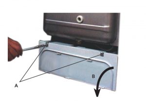
2. Rotate down the B front panel and put it aside together with the screws
3. In order to put the outer case back follow the reverse logic
The C.H. expansion vessel re-pressuring or/and replacement
1. Isolate electricity and water supplies
2. Remove outer panel by looseningall the screws (should be two) at the bottom rear corners
3. Loosen the connections A to expansion vessel as shown on the picture below
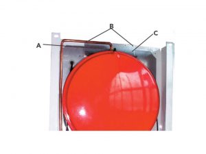
4. Remove screws B and C metal flange
5. Unscrew the expansion vessel from the top of the boiler
6. Re-assemble in reverse order
7. Or re-pressure expansion vessel to the charge value of 0,8-1 bar through the C valve. Make sure that pressure relief value is open (twist about 1/3 of a turn) when repressurizing
Gas valve replacement
. Isolate electricity and water supplies
2. Remove outer panel by loosening all the screws (should be two) at the bottom rear corners
3. Remove all the securing screws (should be two) and lower control panel
4. Disconnect electrical connections from A valve as shown on the picture below
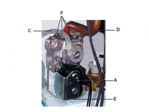
5. Disconnect C plastic tube
6. Loosen the connection on gas pipe and the E gas inlet connection of the boiler
7. Unscrew the two E fixing screw below gas valve
8. Slide out gas valve
9. Remove four F fixing screw on top of the valve and disconnect the gas pipe
10. Remove bottom connection from gas valve. Fit top and the bottom gas connections to the new gas valve
11. Replace following reverse order logic
Air pressure switch replacement
1. Isolate electricity
2. Remove outer panel by loosening all the screws (should be two) at the bottom rear corners
3. Open room sealed department
4. Unscrew the two A screw fixing air pressure switch as shown on the picture below
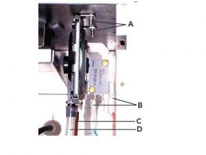
5. Disconnect B electrical leads
6. Remove pressure sensing tubes C&D
7. Note the position of all connections
8. Replace following reverse order logic
Central Heating Temperature Sensor replacement
1. Isolate electricity and water supplies
2. Remove outer panel by loosening all the screws (should be two) at the bottom rear corners
3. Remove all the securing screws (should be two) and lower control panel
4. Find the sensor and disconnect all electrical connection to the sensor
5. Drain the affected service- domestic hot water or central heating D.H.W. or C.H.
6. Unscrew and take away the sensor
7. Replace following reverse order logic
Water Pressure Switch replacement
1. Isolate electricity and water supplies
2. Remove outer panel by loosening all the screws (should be two) at the bottom rear corners
3. Remove all the securing screws (should be two) and lower control panel
4. Find the water pressure switch and disconnect electrical connections. You should now note all the positions to the switch
5. Drain the boiler
6. Unscrew and take away the sensor
7. Replace following reverse order logic
Safety Valve replacement
1. Isolate electricity and water supplies
2. Remove outer panel by loosening all the screws (should be two) at the bottom rear corners
3. Remove all the securing screws (should be two) and lower control panel
4. Find the safety valve and drain the boiler
5. Remove the outlet union from the valve itself and unscrew the union valve connection
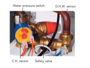
6. Unscrew the fitting of the valve outlet
7. Replace following reverse order logic
Burner replacement
1. Isolate electricity and water supplies
2. Remove outer panel by loosening all the screws (should be two) at the bottom rear corners
3. Room sealed cover must now be removed
4. Disconnect ignition and A flame rectification leads
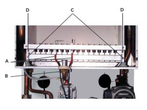
5. Undo B gas rail union
6. Loosen all the screws (should be two) fixing the burner assembly to the D combustion chamber of the boiler
7. Take out the assemply of the burner
8. Replace following reverse order logic
Injectors replacement
1. Isolate electricity and water supplies
2. Remove outer panel by loosening all the screws (should be two) at the bottom rear corners
3. Remove fixing screw on both sides of gas manifold
4. Remove gas manifold
5. Unscrew and remove injectors
6. Clear or change injectors
Limit thermostat replacement
1. Isolate electricity and water supplies
2. Remove outer panel by loosening all the screws (should be two) at the bottom rear corners
3. Room sealed cover must now be removed
4. Find the location of thermostat, if in trouble look at the picture below
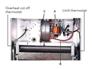
5. Thermostat should now be pulled out from tube, it should be done together with thermostat’s spring
6. All electrical connections should now be removed from thermostat
7. Now spring should be removed from the thermostat
8. Replace following reverse order logic
Fan replacement
1. Isolate electricity and water supplies
2. Remove outer panel by loosening all the screws (should be two) at the bottom rear corners
3. Room sealed cover must now be removed
4. Fan electrical leads should now be disconnected and its positions should be noted
5. The air pressure tubes should now be disconnected from the air pressure switch, its positions should be noted
6. All the screws securing fan assembly (two) should now be disconnected
7. The fan from boiler should be removed
8. The mounting plate should now be swapped over to new fan
9. Replace following reverse order logic
D.H.W. flow-meter replacement
1. Isolate electricity and water supplies
2. Remove outer panel by loosening all the screws (should be two) at the bottom rear corners
3. Take off protective cover from main PCB and unplug flow meter lead from X6 terminal
4. Place a piece of cloth or some other absorbent material over rear of control panel to catch any drops of water that may be released when removing the flow meter
5 Use a 24mm open ended spanner, undo flow meter unions, don’t twist the copper tubing
6. Remove flow meter, check and clean following parts: restrictions, filter, restrictor
7. Fit the new flow meter
8. Reassemble in reverse order
Spark/flame detection electrode replacement
1. Isolate electricity and water supplies
2. Remove outer panel by loosening all the screws (should be two) at the bottom rear corners
3. Open the combustion chamber and open the room sealed compartment
4. Find the electrode, loose the electrical connection from it
5. Remove all the fixing screws and take away the flame detection electrode
6. Unscrew all the fixing screws (should be two) from electrode spark plate and take it away
7. Replace following reverse order logic
Pump replacement
1. Isolate electricity and water supplies
2. Remove outer panel by loosening all the screws (should be two) at the bottom rear corners
3. Remove all the securing screws (should be two) and lower control panel
4. Release pressure from your boiler by using the relief valve
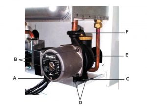
5. Unplug the A pump lead from the head pump as shown on the picture above
6. Place a piece of an absorbent texitle over the rear of the control panel to catch any drops of water that may fall when the pump head is removed
7. Use 4mm allen wrench undo all B allen screws (should be four) in the head of the pump, Unscrew the pump head from the body
8. Fit new head into pump body and secure with the allen screws strongly tightening
9. Replace electrical connection.
10. Disconnect the e expansion vessel connecting pipe from the rear of the pump body by removing the clip from the left hand side
11. Disconnect the return pipe of the boiler and release the pump lower connection by taking away the clip
12. Unscrew all the screws (should be two) on bottom of pump
13. Turn the pump body through 90°, pull the bottom forward and withdraw the pump body
14. Reassemble in reverse order making sure that the O-rings are also replaced
Heat exchanger replacement
1. Isolate electricity and water supplies
2. Remove outer panel by loosening all the screws (should be two) at the bottom rear corners
3. Remove all the securing screws (should be two) and lower control panel
4. Drain heat exchanger for both domestic hot water and central heating
5. Remove front panel sealed compartment
6. Disconnect the central heating limit thermostat and the overheat thermostat
7. Take away the fan, flue hood, main burner and flow meter as described previously
8. Take away the pump to heat exchanger flow connection and locknut
9. Undo the domestic water outlet connection and locknut
10. Lift out heat exchanger
11. Re-assemble in reverse order
After each parts replacement you will need to put your boiler back into operation. In order to start your boiler after parts replacement following steps should be done:
– open the gas cock upstream of the boiler and vent air present in the pipe upstream of the gas valve
– switch on the electrical supply to the boiler and then rotate the ON-OFF-Reset switch into the ON position
– verify the burner pressures, inlet working gas pressure and the gas rate
After this all is set you will need to choose which operating mode you want to switch on: central heating and the domestic hot water production or just domestic hot water production- this mode is usually being switched on only during the summer. If you want to choose central heating and hot water you need to put the knob into winter position, after this set the temperature- above 50°C and set the room thermostat to maximum value. The burner will ignite and your appliance will start to operate automatically, controlled by its control and safety devices. If you want to choose the domestic hot water only put the know into summer position. In the hot water mode only your appliance is will operate automatically when the domestic hot water will be drawn off.
Attention! When after the start-up procedure correct completion, the burners still fail to ignite resulting in the boiler shut down and the warning lamps will light up, you should wait for about 20 seconds then move the knob to RESET position, hold it for a few seconds and then release it. The reset electronic control unit will repeat the start-up cycle.
Shutting down your appliance for longer periods of time
In instances where you want to shut down your boiler for a longer period of time (weeks and days) you should close the boiler isolation gas cock, drain the water from domestic hot water and central heating circuits and turn off the electricity to the boiler. Alternatively, drain the domestic hot water system only and add special anti-freeze to the central heating system.